Vapor Pure Instruction ManualUpdated 6 months ago
 Watch the installation video:
Detailed Instructions
What’s included in the box?
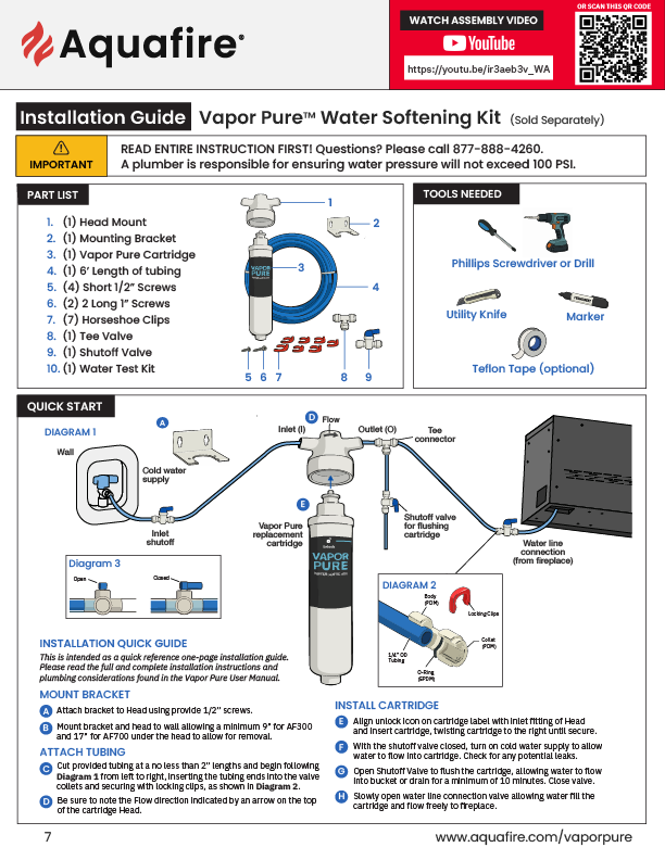
The box should contain the following items:
1 Head
1 Bracket
1 AF Series Replacement Cartridge
1 bag containing:
1 Tee
1 Shutoff Valve
7 Horseshoe Clips
2 Long 1” Screws
4 Short 1/2” Screws- to attach Bracket to Head
12 Hardness Test Strips
1 6’ length of ¼” tubing
Tools/Materials required (Not included):
Phillips Screwdriver
Utility Knife
Permanent Marker
Tape Measure
Safety Glasses
Optional Tools: Teflon tape; Adjustable Wrenches; Drill
Plumbing Considerations:
CONNECT TO A COLD WATER SUPPLY PIPE ONLY.
SHUT OFF COLD WATER SUPPLY PIPE (SEE DIAGRAM 1).
PREVIEW DIAGRAM 1, CONNECTOR FITTING PAGE AND INSTALL CARTRIDGE INSTRUCTIONS.
NOTE FLOW OF WATER “ARROW” ON SYSTEM (SEE DIAGRAM 1).
DETERMINE PLACEMENT OF SYSTEM AND FLOW ARROW DIRECTION BEFORE ATTACHING BRACKET TO HEAD.
HORSESHOE CLIPS MUST BE USED ON ALL TUBING CONNECTIONS OF SYSTEM – FAILURE TO DO SO VOIDS WARRANTY.
FITTINGS PROVIDED WITH SYSTEM MUST BE USED.
USE TEFLON TAPE ONLY ON FITTINGS WITH THREADS. USE OF ANYTHING ELSE VOIDS WARRANTY.
Note the Flow Arrow, Inlet (I), and Outlet (O) fittings on the Head (See Diagram 1).
FLOW DIRECTION OF WATER:
Please see Diagram 1
Water flows from the Cold Water Supply pipe to the Inlet Shutoff to the Inlet fitting of Head.
Water then flows from the Outlet fitting of Head to the Tee, Shut Off for Flushing cartridge, and Aquafire unit or filtered-water dispenser.
MOUNTING OF COMPONENTS and CONNECTING THE TUBING
Please make sure the Lever of Inlet Shutoff will be easy to reach when the system is mounted.
Please make sure the Lever of Shutoff for Flushing cartridge will be easy to reach when the system is mounted.
Installation Location:
Total space needed for complete installation of the AF300: 16” H x 12” W x 5” D.
Total space needed for complete installation of the AF700: 21” H x 12” W x 5” D.
The location selected for the system components should:
Allow space to mount Head. Mount Components only in a vertical/upright position as shown in the Diagram 1.
Provide a solid mount for the Head. Head can be installed under the kitchen sink. However, it can also be installed on a beam/wall in the basement
Allow a minimum clearance of 2” under the Cartridge so that the cartridge can be lowered for easy removal
Allow space on both sides of the Head for the water connections
Check with local plumbing codes and consult your licensed plumber for proper installation.
Installation
Attach Bracket to Head using 4 short 1/2” screws provided.
Using the Bracket as template, mark and then screw in 2 long 1” screws to mount Head in a position to conveniently attach the tubing from the Cold Water Supply pipe to the Inlet Shut off, then to the Inlet of Head, then the tubing from the Outlet of Head to the Tee, Shut off for Flushing, and Aquafire unit or filtered-water dispenser. (See Diagram 1). Allow a minimum clearance of 17” under the Head so that the cartridge can be lowered for easy removal
Mount Head and tighten screws
Turn off Cold Water Shutoff. (See Diagram 1)
See Page concerning Connector Fittings and locate collet
Install Aquafire unit or filtered-water dispenser (Sold separately) using the instructions included with it, but do not run tubing to it at this time. NOTE: Aquafire unit may already be installed.
Install Cold Water Supply pipe attachment (Sold separately) using the instructions included with the pipe attachment. (See Diagram 1). NOTE: Cold Water Supply pipe attachment may already be installed
SECTIONS OF TUBING SHOULD BE A MINIMUM OF 2” IN LENGTH. Cut a length of tubing long enough to connect the Cold Water Supply pipe attachment to the Inlet Shutoff, close to where the Head is mounted. Cut tubing square. (See Diagram 1 and Connector Fitting Page). NOTE: Inlet Shutoff may already be installed and connected to Cold Water Supply pipe attachment.
Connect one end of the tubing to the Cold Water Supply pipe attachment and the other end to the Inlet Shutoff (See Diagram 1 and Connector Fitting Page). If using soft copper tubing, remove burrs and sharp edges. Ensure the outside diameter of tubing is free of score marks. Insert tubing into collet. There will be some resistance when tube is initially inserted. Make sure tubing is inserted all the way into collet until it meets the tube stop, a full 3/4”. Tube may be gripped but not sealed if not fully inserted. After insertion gently pull on the tubing so that the collet around the tubing comes just far enough away from the body of the Connector fitting to be able to slide a horseshoe locking clip between the collet and the Connector body.
Cut a length of tubing long enough to connect the Inlet Shutoff to the Head. Cut tubing square. (See Diagram 1 and Connector Fitting Page)
Connect one end of the tubing to the Inlet Shutoff and the other end to the Inlet Fitting (I) of the Head. (See Diagram 1 and Connector Fitting Page)
Cut a length of tubing long enough to connect the Outlet fitting (O) of Head to the Tee. Cut tubing square. (See Diagram 1 and Connector Fitting Page)
Connect one end of tubing to the Outlet fitting (O) of Head and the other end to the Tee. (See Diagram 1 and Connector Fitting Page)
Cut a length of tubing long enough to connect the Tee to the Aquafire unit or water dispenser. Cut tubing square. (See Diagram 1 and Connector Fitting Page)
Connect one end of tube to the Tee and the other end to the Aquafire unit or water dispenser. (See Diagram 1 and Connector Fitting Page)
Measure 4”-5” of tubing. Cut tubing square. (See Diagram 1 and Connector Fitting Page)
Connect one end of tubing to the Tee and the other end to the Shutoff to Flush the cartridge. (See Diagram 1 and Connector Fitting Page)
Connect the full length of the remaining tubing to the Shutoff to Flush the cartridge. Cut tubing square. (See Diagram 1 and Connector Fitting Page)
Install Cartridge
Align Mark/Dot on cartridge Label with the Inlet Fitting of Head (I) and insert cartridge.
Grasp Head firmly with one hand and with other hand push cartridge up into Head.
Continue grasping Head firmly with one hand and with other hand turn cartridge to the right until it stops, about 1/4 of a turn.
Make sure Lever on Inlet Shutoff has been turned clockwise until it stops in off position. (See Diagram 1)
Open Shut off to Flush the cartridge by turning the lever counter-clockwise so that the lever is in a straight line with the Shutoff body. (See Diagram 1)
Place a bucket under the Shutoff to Flush the cartridge or extend the tubing from the Shutoff to reach a sink or drain
Open Cold Water Supply pipe. Check for leaks from the Cold Water Supply pipe attachment, tubing and Inlet Shutoff
Slowly turn Inlet Shutoff Lever counterclockwise just enough to have water start flowing
Cartridge will now fill with water and begin to flow out of Shutoff to Flush cartridge
Let water run for at least 10 minutes
Slowly turn the lever on Inlet Shutoff counterclockwise until it stops in ON position. Lever of Inlet Shutoff will be straight in line with the body of Shutoff.
Let water run for at least 5 minutes.
Turn Lever of Shutoff to Flush Cartridge clockwise to off position (See Diagram 1), and check for leaks.
Check for leaks within 24 hrs.
Note: Filtered water may appear cloudy for 1 – 3 days as the cartridges are purged of air. You can check to make sure it is only air bubbles causing the cloudiness by filling a large glass with water and letting it stand. The bubbles will rise and the water will become clear. The water is fine to drink. If the cloudiness persists, please contact your local dealer.
Diagram 1

Connector Fittings
Using Connectors, Tubing, and provided horseshoe clips
FOR REVERSE OSMOSIS INSTALLATIONS - USE PLASTIC TUBING ONLY
Connecting the Flexible Tubing
1. Cut a length of tubing long enough for the desired connection. Cut tubing square. If using soft copper tubing, remove burrs and sharp edges. Ensure outside diameter of tubing is free of score marks.
2. Insert tubing into Collet of fitting. There will be some resistance when tube is initially inserted.
3. Make sure tubing is inserted all the way into Collet until it meets the tube stop, a full 3/4”. Tube may be gripped but not sealed if not fully inserted.
4. After insertion gently pull on the tubing to assure that it is secure. By pulling, the collet around the tube will come out far enough from the body of the Connector fitting to be able to slide a horseshoe-shaped locking clip between the collet and the Connector body.
5. Turn on the Cold Water Supply to the system and check for leaks.
6. Check for leaks within 24 hrs.
Using Hardness Test Strips v2
Any Questions? Please call 877-888-4260.
For Test Strips that are Individually Foil Wrapped
Test the New cartridge.
Follow the instructions on the foil wrapper for performing the test.
Match color on strip with color chart on the foil wrapper. Note result.
Test at least once per month.
Change cartridge when the color of the strip matches the color on the bottle corresponding to a number which is equal to or greater than 40, or at least annually.